
IRD8800 - API 670 Compliant Vibration and Condition Monitoring System
Made in India, Made for the World, IRD8800 is a Series of Vibration and Condition Monitoring System which is API 670 Compliant and is used to Monitor and Protect Critical Assets of a Plant such as Motors, Pumps, Fans, Turbines, Compressors, etc.
Salient Features
- Rack-Based 5U High. Available in Racks of Varying widths from 1 Slot to 8 Slots
- Microprocessor Based and User Programmable via Push Buttons for Full Scale Range, Sensitivity, Alarm, Trip and Several other parameters
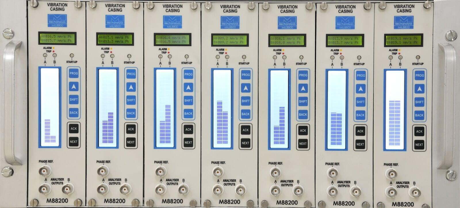
- Alphanumeric Display of Instantaneous value along with configurable Bar Graph Display
- Hot-Swappable Modules compliant to API 670. System can accept Two Independent Power Supplies thereby providing Redundancy in Power Supply
- Industry Standard Outputs - 4-20 mA, Redundant MODBUS RTU/TCP-IP, Alarm and Trip Relay Contacts, Buffered Time Waveform via BNC

Gallery - Photos, Videos and More
Burn-In Test
All Modules, Racks and Panels of IRD8800 manufactured at our Works undergo a Minimum of 4 Hours of Burn-In Test. It is a part of our Standard Practice and an important step in our Quality Check.
If Customers demand - we also carry out 24 hours, 48 hours, 96 hours or 120 hours Burn-in Test as part of Factory Acceptance Test (FAT) prior to dispatch.
During the Burn-in Test - the modules, racks and panels are subjected to the same conditions - power supply, inputs, outputs and ambient temperature and humidity - that they shall face when they are put to use.
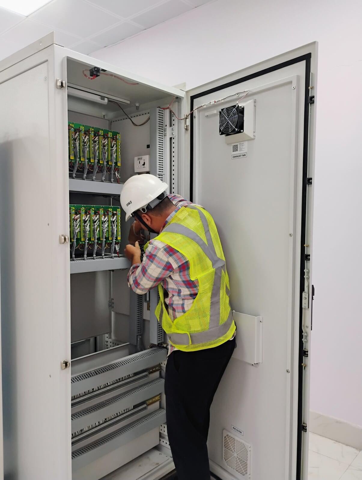
Internal Wiring and Elements of a Panel
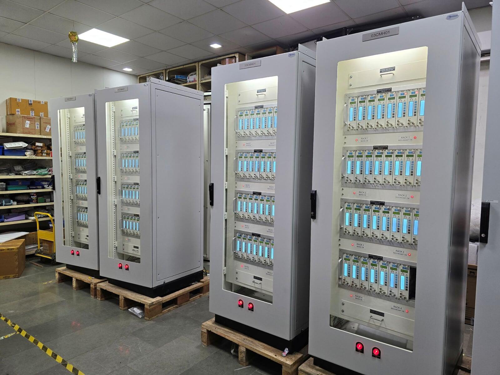
IRD8800 API 670 Compliant Monitoring System is usually supplied in Free Standing Cabinets. These Cabinets can be of Size 2200 (H) x 800 (W) x 800 mm (D) (most popular) or 1500 (H) x 600 (W) x 600 (D) mm. For the convenience of the User, our Panels are equipped with the following as standard:
- Screwless Terminals of WAGO or Connectwell or Phoenix Contact Make for Signal Input, Current Output, Relay Contacts and MODBUS RTU Output connections
- Service Socket of Reputed Make like Anchor Panasonic for Connecting Auxiliaries
- LED Lamp with Door Switch for convenience of User at time of access
- Ventillation and Exhaust Fans for helping in Ventillation to the system and ensuring longevity
- Isolated and Non Isolated Earth Bus Bars
NEXT Button
Being able to quickly view Sensor Bias/Gap Voltages, Alarm Setpoints, Trip Setpoints and Machine RPM is a Boon. To help users of IRD8800 do so - each IRD8800 Module is equipped with a NEXT button. Long pressing it allows the user to see the Bias/Gap Voltages first for each channel, thereafter each press of NEXT button takes user to the screens where they can quickly view Alarm Setpoints, Trip Setpoints, Machine RPM and Firmware Version for the Module.
Getting this information of a Blind Module is a more challenging task and thus we take pride in giving our users this feature for their convenience.
General Specifications of IRD8800 Series Signal Modules
Available Modules and Compatible Inputs
IRD8800 is a Rack Based Monitoring System. The Rack slots can be filled with Hot-Swappable Modules which can be wired to different types of Input Sensors to perform different types of Measurements.
The Table below summarises the module options available and the compatible input sensors for the modules


| Module | Measurement Function | Input Sensor | No. of Channels | Measured Units | Data Sheet |
|---|---|---|---|---|---|
| M88200 | Casing Vibration - It is a measurement of the Absolute Vibration of the Bearing Casing; Keyphasor - It acts as the phase reference point in Vibration Analysis | Accelerometer/Velometer for Vibration; Eddy Current Probe for Keyphasor | 2 for Vibration; 1 for Keyphasor | g Pk, g RMS m/s/s Pk, m/s/s RMS mm/s Pk, mm/s RMS | Data Sheet of M88200-DC |
| M88210 | Relative Shaft Vibration - It is a measurement of the Shaft Vibration Relative to the Bearing; Keyphasor - It acts as the phase reference point in Vibration Analysis | Eddy Current Probes for Vibration and Keyphasor | 2 for Vibration; 1 for Keyphasor | Microns Pk-Pk | |
| M88250 | Casing Vibration - It is a measurement of the Absolute Vibration of the Bearing Casing; Keyphasor - It acts as the phase reference point in Vibration Analysis | Inductive Velocity for Vibration | 2 for Vibration; 1 for Keyphasor | mm/s Pk, mm/s RMS, i/s Pk, i/s RMS, microns Pk-Pk | |
| M88280 | Generator End Winding Vibration - It is a measurement of the Absolute Vibration of the Stator End Winding within a Generator | Charge Amplifier with an input from high temperature charge output accelerometers | 2 for Vibration | LF1 (50/60Hz), LF2(100/120Hz) mm/s Pk, mm/s RMS, i/s Pk, i/s RMS microns Pk-Pk, mils Pk-Pk | |
| M88285 | Absolute Vibration (Stator End Winding Monitoring) | VibroFibre™ FBG, Fiber Optic | 2 for Vibration | microns Pk-Pk | |
| M88300 | Axial Shift | Eddy Current Probe | 2 for Axial Shift | +/- mm, +/- mils | |
M88400 | Cam Valve | Rotary Potentiometer | 2 | %, Deg, mm, inch | |
| M88500 | Differential Expansion* | Eddy Current Probe | 2 | +/- mm, +/- mils | |
| M88600 | Eccentricity | Eddy Current Probe | 2 | microns pk-pk, mils pk-pk | |
| M88700 | Other Parameters (Pressure, PF, Load, etc) | 4-20 mA DC | 2 | User Defined | |
| M88750 | Vibration and Temperature | IRD544M Velocity Input & RTD 3-Wire Input | 2 | mm/s Pk, i/s Pk, microns P-P , mils Pk-Pk Deg C or Deg F | |
| M88800 | Shell Expansion | LVDT | 2 | mm, inch | |
| M88900 | Speed Monitor** | ECP - User Defined | 2 | RPM | |
| M88925 | Reverse Rotation | Dual ECP Input Sensors | 1 | Direction by LEDs | |
| M88950 | Temperature | RTD (3 Wire) | 4 | Deg C or Deg F |
Information available on MODBUS Output
The Redundant MODBUS RTU/TCP-IP Output available per Rack on the Rack Backplane provides the following information for integration in DCS/PLC/SCADA:
- Trip Level Setting
- Trip Hysterisys count
- Trip Fail Safe Logic setting
- Trip Relay Latch setting
- Trip Turn ON Delay time
- Process Value
- Alarm Level Setting
- Alarm Hysterisys count
- Alarm Fail Safe Logic setting
- Alarm Relay Latch setting
- Alarm Turn ON Delay time
- Gap Voltage
- Full Scale Range
- Sensitivity Unit
- Sensitivity Setting
- Display Unit
- Low Pass Filter Selection
- Relay Status
- High Pass Filter Selection
- Noise
- Tx Fail Low Level Setting
- Tx Fail High Level Setting
- Startup Delay Time
- Process Status

Please feel free to reach out to our Sales Team with any questions that you may have about the System and we shall be happy to answer the same. You can send us your requirements for this system using the adjacent Email Button
If you need Help on IRD8800 and need to access relevant articles and download User Manuals, then please follow the adjacent link which will take you to the help center
IRD8800 - Trusted by Companies around the World


